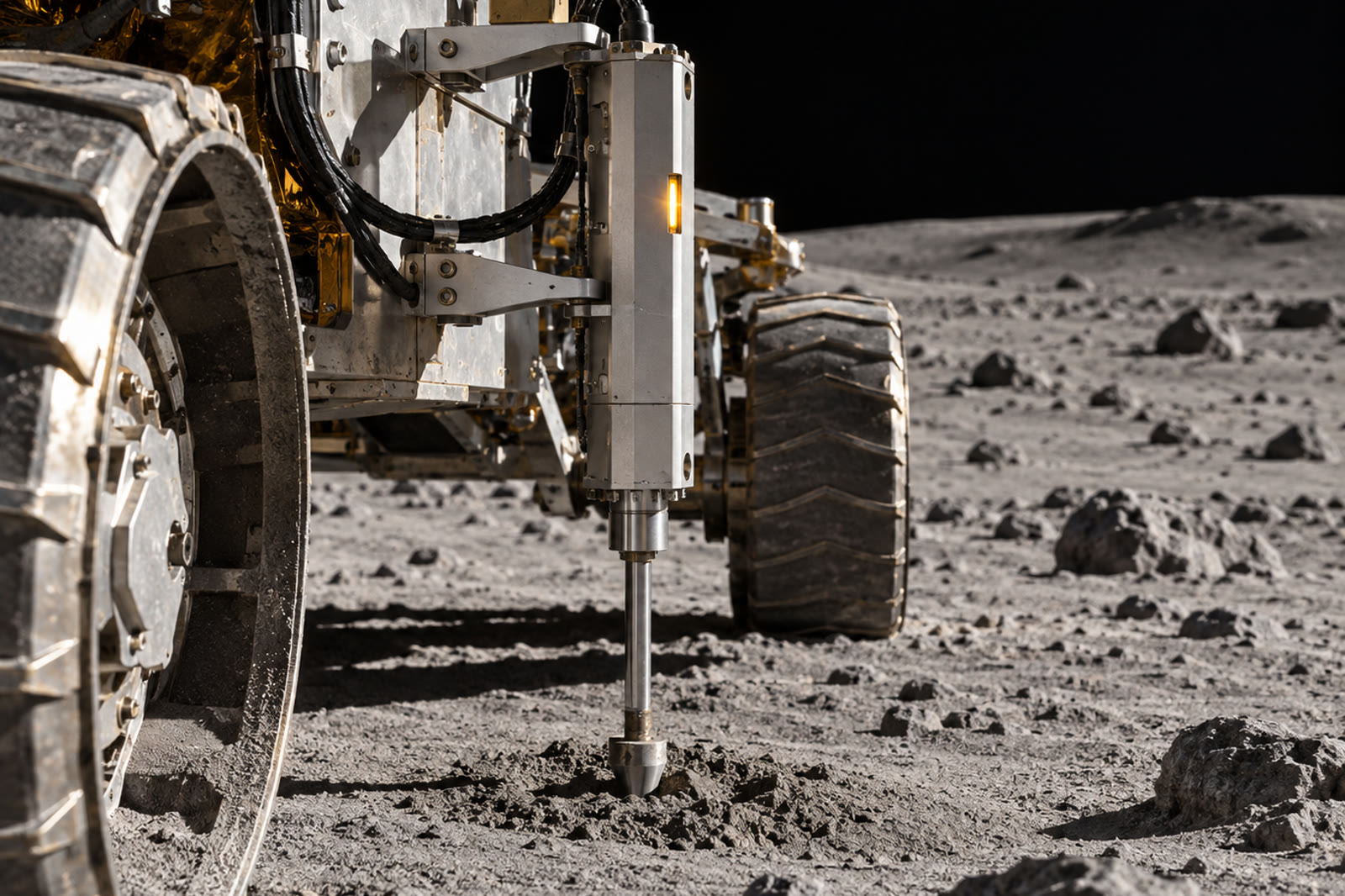
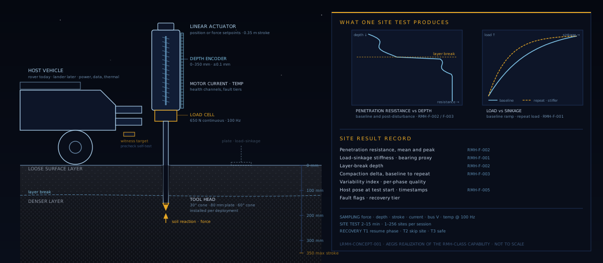
A host-mounted instrument that drives a tool into the regolith under controlled force or position and turns what it feels into engineering numbers: penetration resistance with depth, load against sinkage, layer breaks, and how much the ground stiffens under repeated load. Answers whether a wheel can drive across a patch and a lander can set down on it.
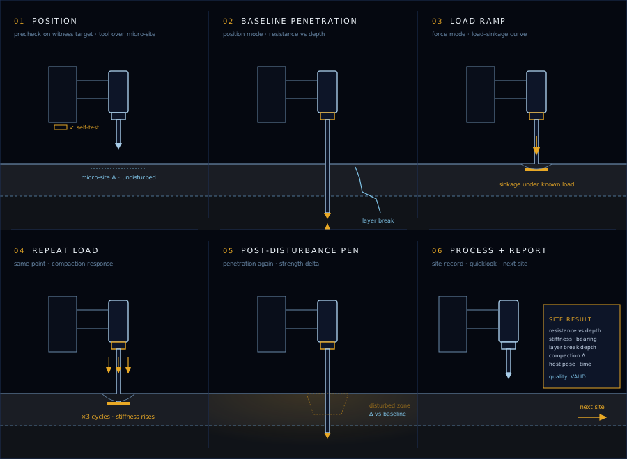
The host vehicle parks, clears the workspace, and issues one command. The instrument walks the phases below on its own and returns a site result. A hard site that saturates force early and a soft site that swallows the tool are both valid outcomes, not faults. Only a genuine hardware fault safes the instrument.
On deploy the tool runs a self-test against a witness target on its own bracket, so a bad load cell or encoder is caught before it touches regolith. The tool is then placed over the commanded micro-site.
Position-controlled penetration at a held rate, recording resistance continuously with depth. The processor picks the largest stiffness discontinuity as the layer break. Reaching the force limit before target depth is recorded as force-limited depth, which is data.
Force-controlled loading at the surface, incremental or continuous, producing the load against sinkage curve. Its slope is the stiffness proxy and, with tool area, the bearing proxy a mobility or landing engineer actually wants.
The same load applied again at the same point, several cycles. The change in stiffness from the first cycle is the compaction delta: how much the ground firms up under traffic.
A second penetration profile through the loaded zone. Compared against the baseline at the same micro-site it quantifies the strength and density change caused by the loading, which is the disturbance-sensitivity requirement made measurable.
Onboard processing reduces every phase to stiffness, bearing proxy, layer-break depth, compaction delta, and a quality flag. A compact site record with the host's pose at test start is written to the data recorder and published for downlink. The host moves on. Sessions run from one site to hundreds.
Command, sequencer, actuator control, sensing, processing, reporting, fault orchestration, and housekeeping on the core Flight System. This is the 2.0 rewrite and the third member of the Aegis flight-software family after the rover and tanker stacks, sharing their layout, HAL pattern, and eighteen recorded architecture decisions.
The complete nine-phase site test runs end to end in a flight-software image against a physics simulator that actually moves the actuator, with the commanded depth reached, repeat-load cycles walked, and a correctly identified site record published. Eight standalone unit-test suites and an end-to-end smoke test pass on every commit.
Limits are watched by the stock cFS Limit Checker and answered by Stored Command sequences, with the instrument's own fault app reduced to a thin orchestrator. Every fault maps to a tier: resume the phase, skip the site, or safe the instrument. Hardware envelopes live in one place with their origin and margin recorded.
The first Aegis flight-software image that rides on another vehicle. It subscribes to the host's pose and velocity so every sample is stamped with where the vehicle was. A bridge turns the packet stream into a live browser console with manual actuator commands routed through the sequencer's safety logic.
The Regolith Mechanics Head page is a requirements page, not a device. It says what an RMH-class investigation must be able to do. Every hard number on this page is an Aegis engineering choice layered on top of it, and a different realization with different hardware would carry different numbers without violating the canon.
The table maps each RMH functional requirement to where it lands in the LRMH flight software. Where a requirement is deferred, that is stated.
| Req | Function | How LRMH addresses it |
|---|---|---|
| RMH-F-001 | Normal load testing | Load-ramp and repeat-load phases under force control. Load against sinkage is recorded directly; stiffness and bearing proxies are computed onboard. Implemented |
| RMH-F-002 | Penetration profiling | Baseline and post-disturbance penetration under position control with continuous force sampling to 350 mm, covering the wheel and footing interaction zone. Force saturation is a valid termination, recorded as force-limited depth. Implemented |
| RMH-F-003 | Disturbance sensitivity | The repeat-load and post-penetration pair operates on the same micro-site as the baseline pair. Compaction delta and strength change are first-class fields in the site record. Implemented |
| RMH-F-004 | Traction correlation (recommended) | Drawbar pull against slip needs a reaction-load reference. The traction phase exists in the state machine as a stub. Whether the reference comes from host wheel torque or a dedicated tether sensor is an open trade, so the phase is deferred to the next development phase. Deferred · open trade |
| RMH-F-005 | Time synchronization | Every sample is timestamped against the flight time base and stamped with the host's cached pose and velocity at acquisition. Host pose at test start is carried in the site record; populating it in the binary record is on the flight-readiness list. Designed · in work |
LRMH is a payload, not a vehicle. Site selection, traverse planning, and the decision to stop and test belong to the host's flight software and to ground tools outside the instrument's envelope. The instrument owns what happens between the start command and the site record.
That split is why the same instrument image can move to a lander later. The host interface is a telemetry subscription and a handful of commands, and the hardware abstraction below the apps has simulation, bench, and flight backends with the mission apps unchanged across all three.
Regolith mechanics and ice prospecting are paired capabilities: the WOK prospecting rover asks whether the ice is there, LRMH asks whether a vehicle can get to it and a plant can be set on it. Both trace to requirements pages that predate the vehicles.
The software proves the sequencing, the fault posture, and the data path. It does not prove the geotechnics. The regolith model is deliberately opaque to the flight software, which means the physics in the simulator is a placeholder until a testbed says otherwise.
The simulation backend is complete. The bench backend is specified and stubbed pending mechanism hardware. The flight backend is empty and awaits a flight controller. Everything above that line is done.
Resistance and bearing fields are computed and carried, but conversion from newtons to kilopascals waits on a loadable tool table with measured tip areas and calibration shape from the mechanism partner.
The recommended traction correlation needs a reaction-load source. Host wheel torque is cheap and indirect. A tether sensor is direct and adds hardware. The trade is open and the phase is deferred until it closes.
Cone index to bearing capacity in lunar regolith, plate scale sensitivity, penetration rate effects, and what a compaction delta means for traffic. These are testbed questions, and the people who run regolith testbeds are who this page is for.
Discussion welcome through the engagement page.