05 — Flight Software & Crew Operations Console
NASA cFS-Based Avionics with Real-Time Operator Awareness
The Aegis-Class Rover flight software is built on NASA's Core Flight System (cFS) — the same
flight-heritage framework used across NASA missions. The stack runs end-to-end in simulation
today: all 16 applications build and execute, and the autonomous safing chain has been
exercised live against injected sensor faults. Mission-application source is identical across
simulation, bench, and flight targets — only the hardware abstraction layer changes between
them — so verification done in simulation carries forward rather than being rebuilt for each
environment.
Development status: The flight software runs end-to-end in a desktop
simulation — a real cFS workspace, all 16 applications, with autonomous FDIR verified live
across the full safing chain.
Bench and on-vehicle targets share the same source through the HAL; no flight hardware is committed.
16
cFS Applications
cFE core + 9 standard cFS + 7 Aegis mission apps
5
FDIR Safing Modes
NOMINAL → THERM_SAFE → ECLSS_SAFE → LOADSHED → SHELTER
20 Hz
Navigation Rate
aegis_nav navigation & odometry update
CCSDS
Telemetry Protocol
Standards-compliant
WebSocket
Console Live Link
CCSDS-UDP ↔ browser bridge, same schema every env
cFE
Core Flight Executive
Runtime — NASA flight heritage
Autonomous Fault Detection, Isolation & Recovery
The flight software continuously monitors watchpoint signals across thermal, life support,
electrical, and radiation domains. When a watchpoint excursion is detected, the system
autonomously transitions through the safing chain without requiring crew action. Each mode is
a known operational posture with documented entry conditions, system reconfigurations, and
crew advisory protocols. Crew override authority is preserved at all levels.
Autonomous Waypoint Navigation with Energetic Range Gating
The navigation system maintains a waypoint catalog and a guidance state machine for autonomous
traverse to selected destinations. Reachability is not gated by a static geometric range; it is
gated by live state-of-charge, vehicle load, and multi-hop reachability through LUNET surface
utility nodes. The planner accounts for available recharge stops along candidate routes,
providing crew with reachability information that reflects actual energetic constraints rather
than nominal range estimates.
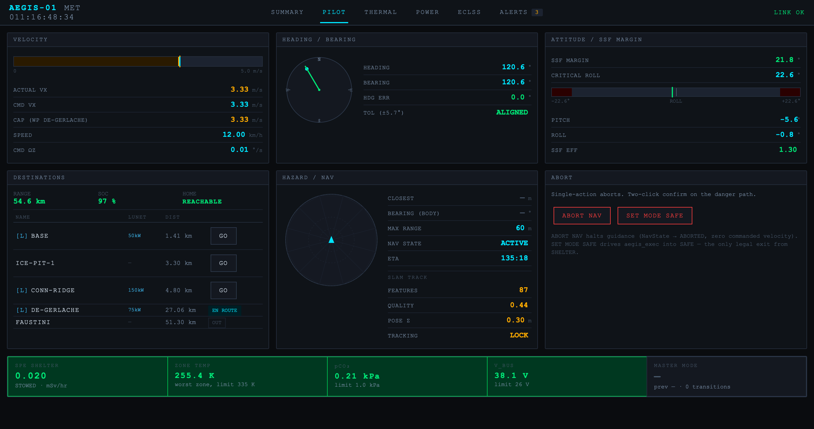
Crew Operations Console
The crew operations console is a browser-based real-time interface for situational awareness
and command authority. Pages cover summary system status, navigation and waypoint management,
power and thermal, atmosphere and life support, pilot view, and contingency recovery. The same
console operates identically across simulation, bench, and flight — supporting consistent
operator training and procedure validation across mission phases.