ESIC-Class Hull Inspection Free-Flyer

AHIDAegis Hull Inspection Drone

A resident cold-gas free-flyer that inspects the outside of a crewed station without an EVA. It navigates in the frame of the surface it is inspecting, so every image, thermal frame and point cloud is keyed to a cell of the structure and can be flown again on the next sortie. Scheduled surveys, post-event checks, repair verification: the operator owns the products and the vehicle lives on the hull.

8
cFS Flight Apps
324
Cells · One Module · One Sortie
1.0 m
Standoff · Surface-Frame Navigation
// 01 Vehicle Render
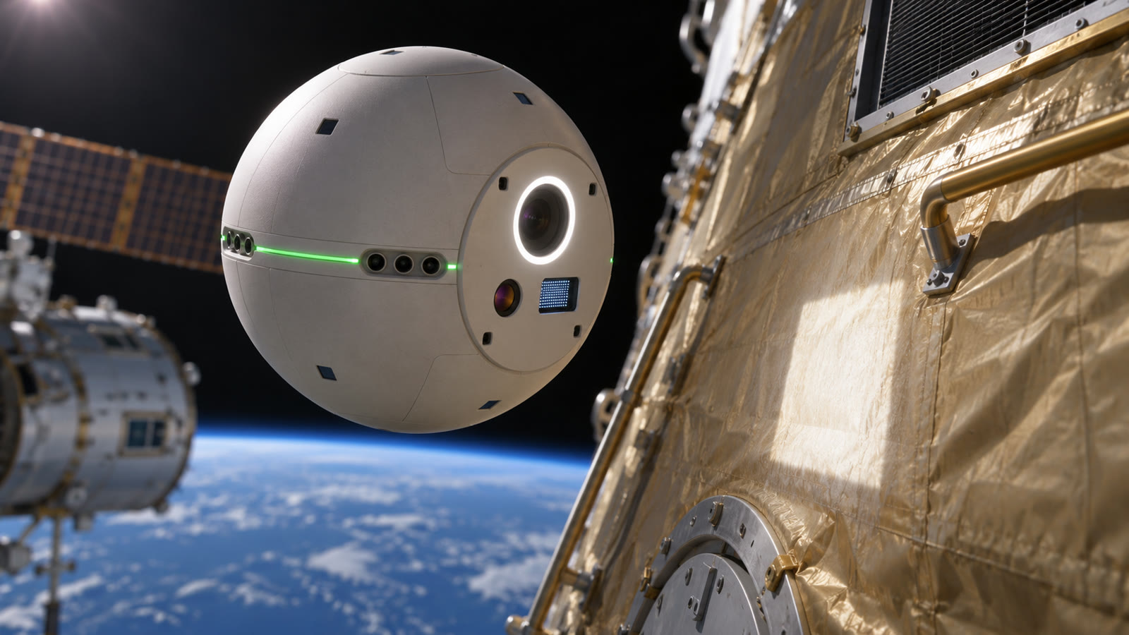
AHID at standoff over a station module: a matte spherical free-flyer with its work face toward the gold multi-layer insulation of the hull, the inspection camera in its illuminator ring lit, a green status ring around the body, Earth below
FIG. 01 — AHID at standoff over a module, work face toward the hull: the inspection camera in its illuminator ring, the thermal and mapper apertures beside it, the four range-beam apertures at the corners of the face, proximity windows and thruster ports flush in the body, the status ring lit. AHID-RENDER-001 · CONCEPT ART
// 02 The Surface Grid
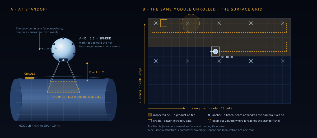
Left: AHID holding one metre off a station module with four range beams meeting the hull at the corners of its camera footprint. Right: the same module unrolled into a grid of cells with the scan path, anchors, cradle and a keep-out marked.
FIG. 02 — The organizing idea. Each inspectable surface in the station model is a named frame: u along it, v across it (wrapping around a cylinder), h along the local normal. The camera footprint at standoff tiles (u, v) into cells; a cell id is a fixed patch of structure. Coverage is "every tasked cell has a product", repeatability is "fly the same cell ids again", localization is "cell id plus the surface's transform". A curved surface costs nothing extra: v wraps, the normal rotates, and the range beams measure both. AHID-FRAME-001 · NOT TO SCALE
// 03 Sortie — Cradle to Cradle

The operator loads a task list of cell blocks on named surfaces and gives the release. The vehicle flies the phases below on its own and comes home with a coverage report: cells tasked, inspected, skipped and why. The operator can hold, return or safe it at any time, and resumes it from a hold. There is no joystick in the baseline.

PHASE 01

Docked and Undock

Charged, filled with nitrogen and off-loaded by wire at a cradle on the hull. On release it backs away at low speed on the cradle's own anchor until it is clear of the cradle volume.

PHASE 02

Transit

Free flight in the station frame to the approach point of the next surface, dead-reckoned between fixes under a speed cap, with every active keep-out volume checked against the path. Entering one is a hold, and the operator is told why.

PHASE 03

Acquire

The range beams see the surface; the vehicle settles to standoff, aligns to the local normal, takes its first anchor fix on a feature of the station model, and switches its navigation into the surface frame. About a minute.

PHASE 04

Scan

Rows along the surface at scan speed, a cross step between rows, a capture at every cell: a visual frame, a thermal frame and, where tasked, a point cloud, each with a cell record. Anchors re-fix the position as they pass; between them the surface-facing camera's flow odometry carries it. One module is 324 cells and about 36 minutes.

PHASE 05

Return and Dock

Transit back on the station frame, approach on the cradle's anchor, capture. The coverage report is written at the cradle and the products off-load by wire. Low nitrogen or low charge during a scan brings it home early, with the untouched cells listed as skipped.

ANY PHASE

Hold, Reacquire, Safe

A hold parks the vehicle at standoff on its current cell: degraded navigation, a keep-out activation, a valve verdict or an operator command. Reacquire re-establishes the frame after a hold. Safe nulls the relative velocity, closes the valves and waits for the operator: a lost standoff measurement, lost attitude knowledge or a stuck valve gets that.

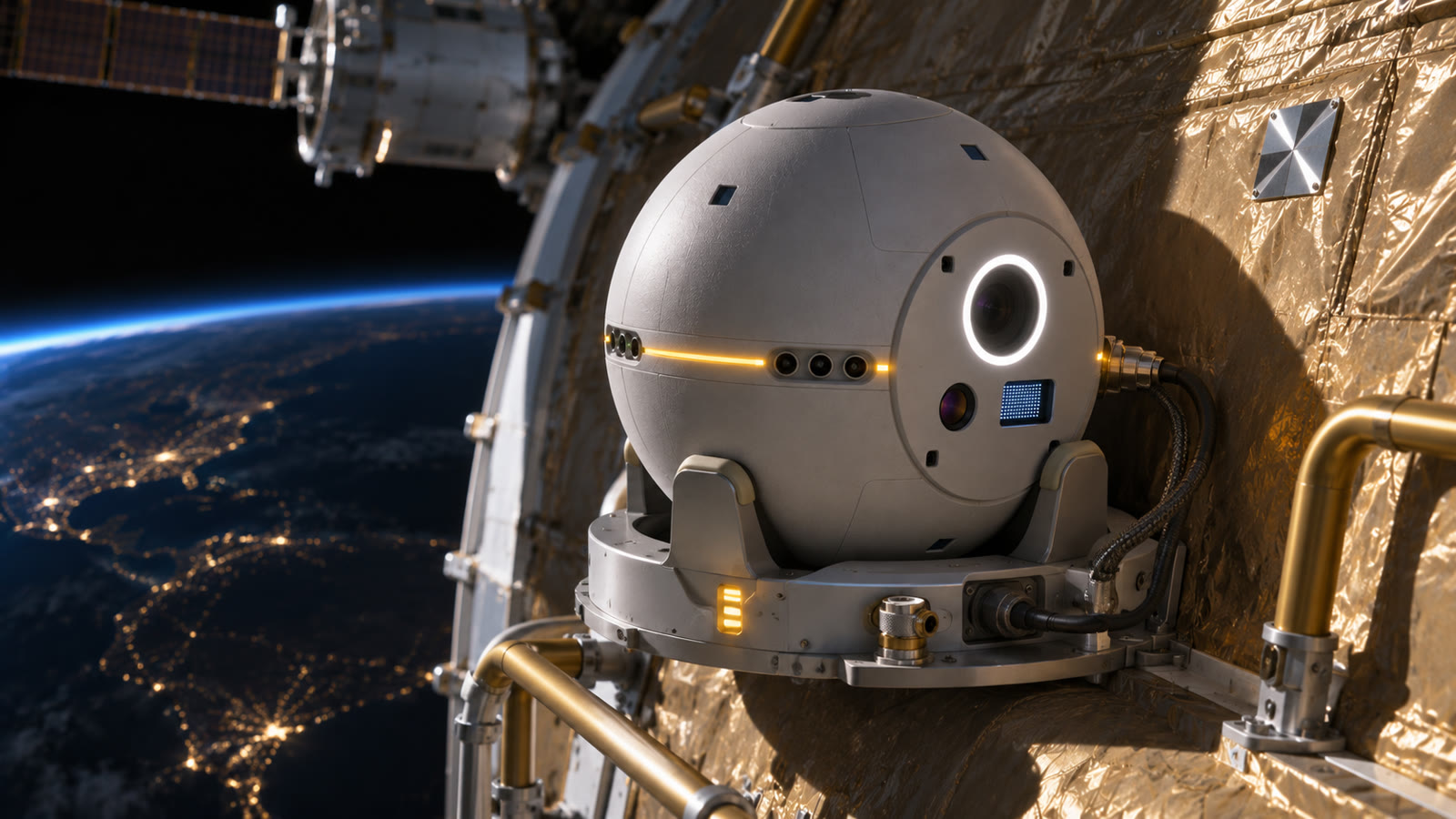
AHID seated in its cradle on the hull at night: three capture arms around the sphere, a nitrogen line and a data connector at its rear, an amber charging ring, a marker plate on the insulation nearby, city lights on Earth below
FIG. 03 — Docked. The cradle is where a sortie starts and ends: contact power, a nitrogen fill and the product off-load by wire at every docking, the capture arms around the sphere, the status ring amber while it charges. A marker on the hull beside it. AHID-RENDER-002 · CONCEPT ART
// 04 A Sortie With Faults, in the Flight-Software Image
FIG. 04 — A whole-module sortie and a panel, flown by the flight software image against its physics simulator and recorded from the live telemetry, played at twenty times mission time. Three faults are injected on the way and each is recovered: a keep-out volume switches on across the scan and the vehicle holds until it is cleared; a thruster valve dies and the fault chain holds the vehicle until the operator resumes it on the eleven that remain; a range beam drops out and the navigation carries on with three. The gauges show the nitrogen and charge spent. AHID-TAPE-002 · SIMULATION · REFERENCE STATION MODEL

What the player draws is what the flight software published: its estimated position on the grid, its target, the cells it has captured, the four beams, the twelve pulses it commanded this control period, the valves the driver reports open beside them, the tank, the battery, and the stock cFS Limit Checker's watchpoints and actionpoints. The station is the reference model the requirements review uses, a 4.4 by 10 m module and a 3 by 6 m panel, not any real vehicle.

The sizing model was written before the software and then checked against it. The model's figure for a module scan is within 2 % of what the controller spent in simulation, and the cradle-to-cradle sortie within 10 %. That agreement is the point of flying it: the budgets are now numbers with a flown counterpart, not a spreadsheet alone.

// 05 What Exists Today
FLIGHT SOFTWARE

Eight Apps on NASA cFS

Executive, navigation, guidance and control, propulsion, sensing, data, power and link, on the core Flight System. The sixth member of the Aegis flight-software family after the rover, hopper, tanker, WOK and LRMH stacks, on their layout, their hardware-abstraction pattern and their lockstep simulation rule. The navigation runs in the surface frame during a scan and in the station frame in transit; the guidance flies a serpentine over the tasked cells and allocates the twelve thrusters so none exhausts toward the hull.

VERIFICATION

Whole Module Flown, Seven Faults Caught

A six-degree-of-freedom simulator with the station model, surface-relative sensors and an injectable fault set. First light, a two-surface sortie and the whole 324-cell module have been flown end to end in the flight-software image, with every cell captured and the coverage report written. Seven scripted fault scenarios pass on the image: a stuck valve, a dead valve, lost range beams, a flow dropout, a keep-out, low nitrogen and a stalled simulation clock. The standalone test suites run on every build.

FAULT MANAGEMENT

Standard cFS FDIR, Three Responses

The stock Limit Checker watches the published telemetry and the Stored Command app answers: hold for a degraded fix, a dead valve or a low standoff; return home on low nitrogen or low charge; safe the vehicle, master valve closed, for a lost frame or a stuck valve. The propulsion app judges every thruster command against what the valve driver sensed and declares a stuck or dead valve itself.

GROUND

Console, Products by Cell, Tape Player

A bridge turns the packet stream into a browser console: the task editor, the phase commands, a sortie map that fills cell by cell, a product viewer keyed by cell id reading the coverage report, and the tape player live on the same stream. Every telemetry field the console decodes is pinned by a round-trip test against the flight structs.

SOURCE

Proprietary, Open to Partners

The flight software, its simulator, the console and the player are complete and are proprietary to Aegis Station. They are not slated for public release. Proximity operations and relative navigation around a crewed station are also content Aegis Station treats as export-controlled until it is classified. The work is open to partnership: Aegis Station shares the code for evaluation with qualified US organizations under a non-disclosure agreement. Station operators, propulsion and mechanism partners who want to see it against the boundary described on this page can write to contact@aegisstation.com.

Validated In Simulation
Surface-Frame Navigation, Cell-Keyed Products
Whole Module, 324 of 324 Cells
Seven Injected Faults via LC/SC
Sizing Model Within 2 % of the Flown Scan
Nothing Flight-Qualified
// 06 Traceability to ESIC
Capability Definition
ESIC
The Extravehicular Structural Inspection Capability page defines the class: four functional requirements and the data products, with no vehicle, propulsion or sensor prescribed. AHID is one realization of it.

The ESIC page is a requirements page. It says what an inspection capability for a long-duration pressurized platform must do and leaves the how open. Every number on this page is an Aegis engineering choice layered on top of it.

The table maps each ESIC requirement to where it lands in the AHID design and its flight software. Where something is designed but not yet in the software, that is stated.

ReqFunctionHow AHID addresses it
ESIC-F-001 Extravehicular access A resident free-flyer on a hull cradle: undock, transit in the station frame, acquire a surface, scan, return and dock, all onboard from one release. Keep-out volumes, including EVA volumes, are checked in flight and hold the vehicle.
Implemented in simulation
ESIC-F-002 Repeatability A cell is a fixed patch of structure. A task list is a set of cell ids, so the same cells are flown again at the same standoff, on the same normal, at the same heading, under the illuminator's repeatable light. The first survey of a cell is its baseline; later sorties ask whether it still looks like itself.
Implemented Per-cell baselines designed · ground work
ESIC-F-003 Localization Every product carries its surface id, cell id, the pose it was taken from and the sortie it belongs to; the surface's transform in the station model turns a cell into station coordinates. Position comes from range beams for standoff and normal, flow odometry along the surface and anchor fixes on features of the station model.
Implemented
ESIC-F-004 Data usability Visual, thermal and geometric products are files keyed by cell beside a plain-text coverage report; the console shows them by cell with no vendor tooling. Change detection against the previous products of the same cell ids runs on the station or the ground.
Implemented Change detection designed
// 07 Key Parameters
PROJECT ENGINEERING ENVELOPES · MEASURED IN SIMULATION WHERE MARKED · NOTHING MEASURED ON HARDWARE

Vehicle

Body0.5 m sphere, compliant shell, no protrusions
Wet mass8.5 kg (TBR)
PropulsionCold-gas nitrogen, 12 thrusters, 0.50 kg fill
Battery138 Wh, about 3 h of sortie
PrecedentAERCam Sprint (1997) · Astrobee

Navigation

Frame in scan(u, v) on the surface, h on its normal
Standoff1.0 m
Sensors4 range beams · flow camera · IMU · 8 proximity
FixesAnchors: hatches, seams, handrails in the station model
TransitStation frame, dead-reckoned, 0.30 m/s cap

Products

Footprint · cell1.15 × 0.83 m · 0.58 × 0.81 m pitch
Visual12 MP, fixed focus at standoff, LED ring
ThermalRadiometric LWIR, 640 × 512 class
GeometryShort-range mapper, 5 mm pitch, where tasked
Per module324 cells · about 2 GB with the mapper

Sortie

Scan speed0.10 m/s · one module about 36 min
Nitrogen, module sortie166 g as flown in simulation
Sorties per fillAbout 3 as flown · 1.1 with 100 % contingency
ServicingFill, charge and off-load at every docking
ResponsesHold · return · safe
// 08 Host Platform
Baseline Host
Any Crewed LEO Platform
The design host is a non-rotating, human-rated low Earth orbit station of ISS or commercial-station class. Aegis Station's rotating rings are a later variant: a torus with a fixed spin is still a surface in the station model.

AHID is built for Aegis Station, and like the hopper its usefulness comes first. Every long-duration pressurized platform accumulates micrometeoroid and debris strikes, thermal-cycling fatigue and joint wear that cannot be seen from inside, and today the only answers are an episodic EVA or whatever imagery happens to exist. A resident inspector that re-flies the same cells on a schedule is a capability the commercial stations will need before any ring is built.

What the host provides is small: a cradle on the hull with contact power, a nitrogen port and a data connector; a station model naming the surfaces, their anchors and the keep-out volumes; and a safety process the vehicle flies under. What the host gets is a product database keyed to its own structure, and a vehicle that holds or safes itself, master valve closed, the moment its own measurements say it should.

The safety case cannot be written by Aegis alone. The two flown precedents, AERCam Sprint outside the Shuttle and Astrobee inside the ISS, set the shape of it, and host engagement on it is the first item of the next stage.

// 09 Open Items — Where It Stops
Program Context
Analysis, Then Bench
The software stage is done. The analyses that close the mass and thermal budgets are not started, and the next layer of evidence is sensors and thrusters on a bench against real hull surfaces.

The software proves the navigation frame, the sortie sequencing, the fault posture and the product path. It does not prove the sensors on a real hull, the thrusters, or the safety case. The simulator's surfaces, lighting and valves are models until a bench says otherwise, and the page says so wherever a number came from them.

Open 01

What the Flown Software Found

Two gaps the live runs exposed and the roadmap carries: a hold with the anchors just out of the footprint waits out its timeout instead of searching for one, and a keep-out left active across the return path is retried at every hold timeout rather than routed around. Both are on the list, with a bound on hold cycles.

Open 02

Thermal, Plume, Fault Trees, Mass

A lumped thermal model of the sphere, a plume-impingement estimate for the hull and the host's sensors, hazard fault trees for collision and a stuck valve, and a mass rollup from a candidate parts list. The propulsion, battery and instrument fractions are the only allocations with a model behind them.

Open 03

Sensors on Real Surfaces

Range beams and flow odometry against MLI, radiator panels and handrails under the illuminator, with introduced defects, for the per-cell baselines and change detection. Thruster and valve characterization. A cradle concept with a mechanism partner; none exists at this scale.

Open 04

The Safety Case and a Host

Operation near crew and near an EVA needs a host's process and the precedents' lessons. Then an air-bearing demonstration with the flight software unchanged, and a technology demonstration on a host station under its own safety process.

Discussion welcome through the engagement page.

← Back to Aegis Station