// 01
Fleet Render

FIG. 01 — LTF-MK1 Loaded Configuration, Lunar Surface — Water Cartridge Mounted
LTF-RENDER-001
45 autonomous tankers. 3.3 million metric tons. A continuous cycle of ascent, delivery, and return — building humanity's first orbital city one payload at a time.
The fleet's first operational mission is lifting the first ISRU cartridges to the Lunar Orbital Propellant Depot. Single vehicle, low cadence — enough to commission end-to-end propellant production before the shield-fill campaign begins. Depot first light does not require full fleet deployment.
Sustained surface-to-LLO water delivery to Aegis Station shield reservoirs. Fully autonomous operations across continuous 2,600 m/s ascent-and-return cycles. This is the requirement that sizes the full ~45-vehicle fleet — not depot operations.
From first light onward, depot resupply runs in parallel with the shield-fill campaign and continues indefinitely after it. The depot is the fleet's first customer and a permanent one — not a post-fill handoff. Post-fill, the same cycle extends to EML1/2 hubs and deep-space propellant staging.
Ballistic surface hops between ISRU nodes for LOX and water redistribution. 160–940 m/s per hop — up to 6× sorties per orbital propellant load. Becomes operationally relevant once multiple ISRU nodes are producing at capacity.
1–2 tankers maintained in standby at all times. Emergency water delivery to crewed outposts achievable within 6–8 hours of dispatch authorization.

The Modular Tank Cartridge (MTC) is the fundamental unit of the LTF logistics chain — a standardized, self-contained water vessel designed for drop-in handling at every point from the ISRU node to the Aegis Station shield reservoir. The cartridge is not a component of the tanker; it is cargo that the tanker carries. This distinction is the key to the system's operational simplicity.
Per-vehicle flight software implementing the full mode FSM, propulsion feed control, autonomous safing, and CCSDS command/telemetry. Multi-vehicle simulation exercising 45 concurrent instances through complete sortie cycles — ascent, orbital insertion, station capture, cargo swap, deorbit, and surface return.
Fleet-level dispatch scheduling, pad deconfliction, station berth queuing, and telemetry-gated ground operations across the full vehicle complement. The sortie cycle runs autonomously with real-time cargo and propellant state verification at every transition — no operator in the loop for nominal operations.
The LTF tanker requires no structural redesign for surface-to-surface operations. Its VTOL architecture and LOX/CH₄ propulsion are inherently suited to ballistic hops between ISRU nodes — ascending on a near-vertical vector, coasting at low altitude, and performing a precision landing at the destination pad.
This capability transforms a collection of isolated extraction points into an integrated logistics network, allowing surplus LOX and water to flow to nodes in deficit rather than being vented or stockpiled past capacity.
High-yield nodes producing excess liquid oxygen redistribute to nodes in deficit. Delivered LOX feeds directly into tanker refueling operations at the destination, creating a shared propellant pool across the network.
ISRU extraction failure at a crewed outpost triggers autonomous dispatch from the nearest surplus node. First delivery achievable within 6–8 hours — no crew or operator action required at the origin site.
New exploration outposts 900+ km from the nearest ISRU hub receive propellant caches via a series of surface hops, establishing operational independence before local production comes online.
3–5 tankers operate in dedicated S2S rotation, executing scheduled monthly rebalancing of LOX and water inventories across all active nodes under autonomous dispatch control from Aegis Station.
The Moon has abundant water ice. Electrolysis splits that water into liquid oxygen and liquid hydrogen — the two highest-performing chemical propellants available. The LTF's ISRU nodes are already producing both as a consequence of the shield-fill operation itself. LOX feeds directly into the current propulsion system. Hydrogen has been the missing piece.
The missing piece is now on a credible engineering path. Blue Origin's Lunar Permanence team has demonstrated zero boil-off storage of liquid hydrogen at 20K — the temperature at which LH₂ must be maintained — at twice the performance of the previous state of the art. Active cryocooling powered by the node's solar and fission power supply keeps propellant cold indefinitely, with no boil-off losses.
The program consequence is significant: rather than importing methane from Earth on every resupply cycle — a permanent, compounding dependency running into the tens of billions annually at fleet scale — the LTF transitions to a fully closed propellant loop. Water in, LOX and LH₂ out. No Earth supply chain. No launch-dependent consumables. A logistics system that is genuinely autonomous.
Fleet operates on proven LOX/CH₄ propulsion while LUNET nodes are built to the full 50 kW power specification. Methane import costs are accepted during this period as the cost of mission reliability. Cryogenic and fission infrastructure is commissioned in parallel — not retrofit later.
Node cryocoolers and LH₂ storage come online. Tankers are qualified for liquid hydrogen service. The fleet transitions progressively — early vehicles flying LOX/LH₂ missions as nodes are certified, methane imports tapering as the conversion progresses across all six LUNET sites.
Full fleet operates on locally produced propellants. Zero Earth import dependency. The higher Isp of LOX/LH₂ reduces propellant mass per mission, increasing payload fraction and compressing the remaining fill timeline. Post-fill, the same fleet serves Aegis Station depot and surface logistics roles indefinitely.
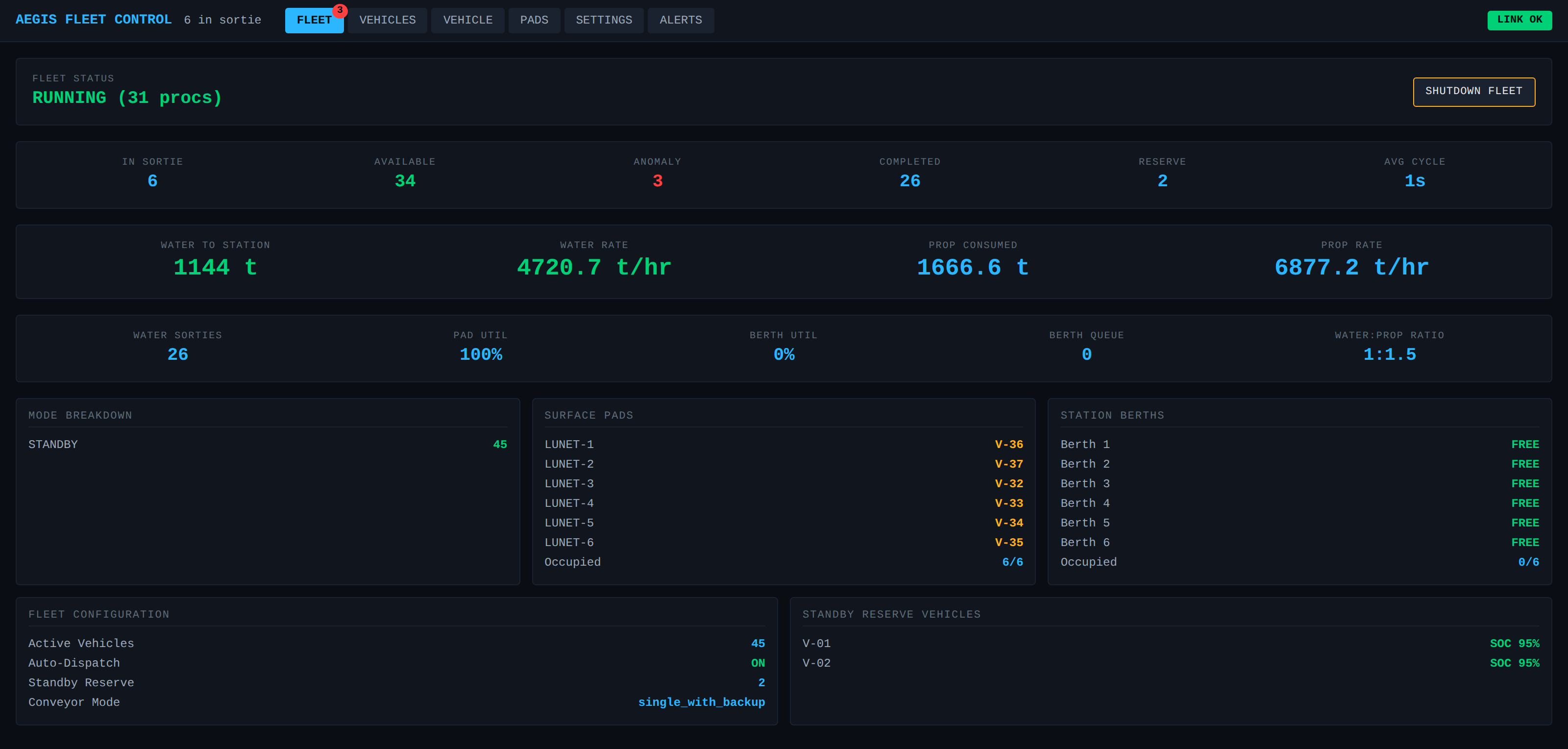
The tankers fly themselves. Coordinating them — deciding who flies the next sortie, keeping one ship to a pad, healing the schedule around an anomaly, and squeezing maximum water to station — is the job of the ground-side Fleet Commander.
Open the Fleet Commander →