Aegis Orbital Compute Node (AOCN)
LEO compute architecture constrained by power generation, heat rejection, and serviceability
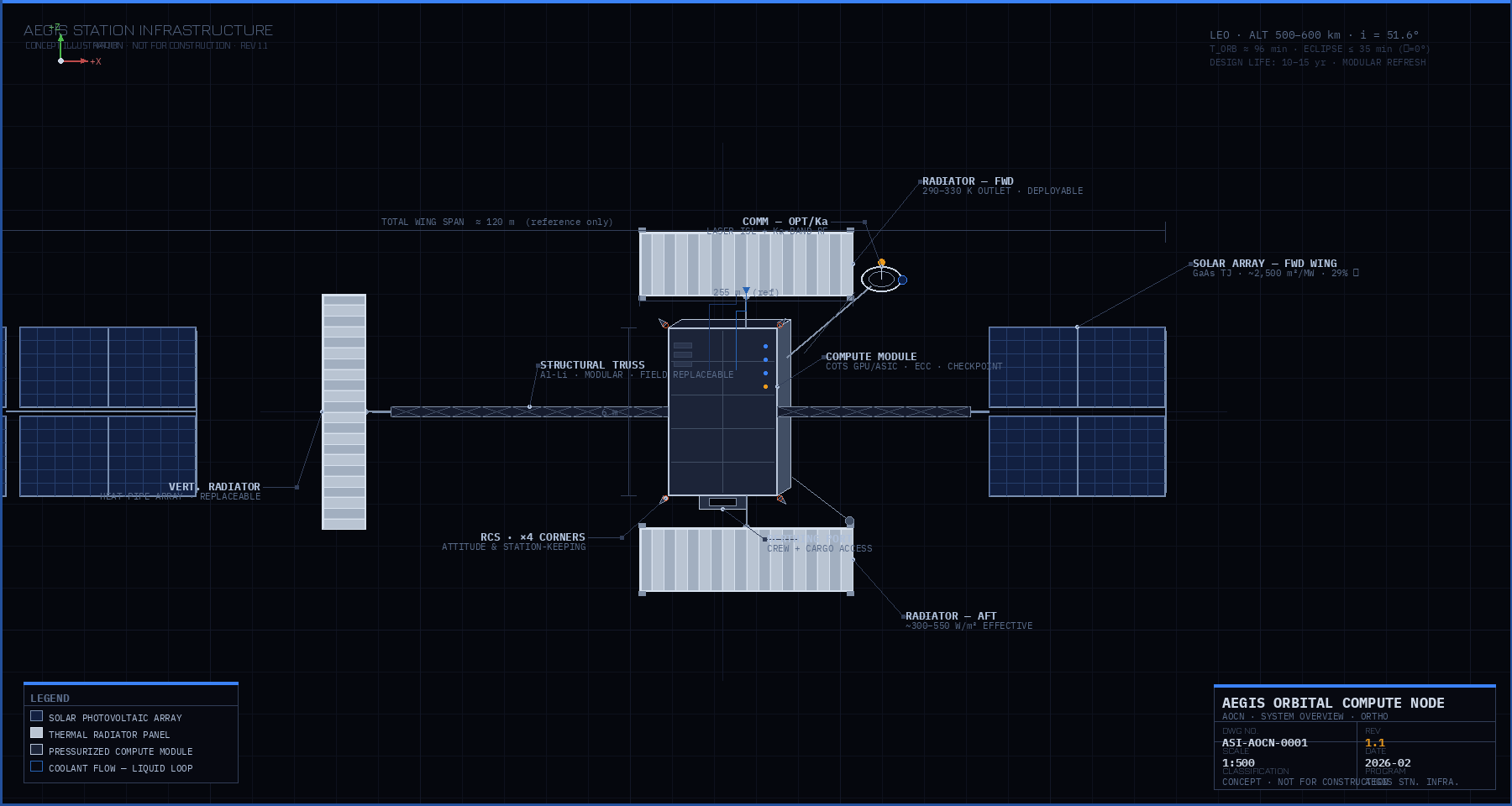
The Aegis Orbital Compute Node (AOCN) is a modular compute platform intended for deployment in Low Earth Orbit (LEO). The architecture is sized and organized around first-order physical constraints: electrical power generation, waste heat rejection, radiation environment, and on-orbit serviceability.
AOCN is not intended to replicate terrestrial data centers in orbit. It is structured as an orbital compute accelerator for workloads where power density, thermal isolation, or space adjacency dominate over latency or interactive access.
At steady state, essentially all electrical input power is rejected as heat. Radiator geometry, operating temperature, and loop architecture therefore set the upper bound on continuous compute output. Solar array area is a comparable structural driver that was understated in prior documentation.
The prior version stated a radiator operating temperature of 350–450 K alongside a heat rejection rate of 500–1,000 W/m². These figures are internally inconsistent. The Stefan-Boltzmann law governs radiative heat rejection; at 350–450 K, a two-sided panel with emissivity ε ≈ 0.88 would reject 1,500–4,100 W/m², not 500–1,000 W/m². The lower figure is only consistent with much cooler operating temperatures.
The correct framing depends on which constraint drives the design:
Commercial GPUs have junction temperature limits of approximately 363 K (90 °C). A practical cooling loop delivers coolant to the radiator at roughly 300–330 K after accounting for thermal resistance across the cold plate and heat exchanger. At these temperatures, the two-sided rejection rate is approximately 490–760 W/m² (theoretical), falling to 300–550 W/m² after applying a 0.6 effective factor for solar loading, view-factor losses, and degradation margin. This supports a radiator area requirement of roughly 1,800–3,300 m² per MW.
If a different compute architecture (e.g., high-temperature ASICs or future hardware) can tolerate junction temperatures allowing 350–400 K coolant outlet temperatures, the effective rejection rate rises to approximately 900–1,500 W/m², reducing area requirements to roughly 650–1,100 m² per MW. This path is not consistent with current COTS GPU constraints.
Revised working assumption for AOCN v1.0 (COTS hardware baseline): radiator outlet temperature 290–330 K, effective heat rejection ~300–550 W/m², radiator area 1,800–3,300 m² per MW. The prior upper bound of 5,000 m²/MW is overly conservative; the prior lower bound of 2,000 m²/MW remains within range.
| Radiator Outlet Temp | Two-sided Rejection (theoretical) | Effective (~×0.6 margin) | Area per MW (effective) |
|---|---|---|---|
| 275 K (2 °C) | 571 W/m² | 343 W/m² | 2,920 m² |
| 300 K (27 °C) | 808 W/m² | 485 W/m² | 2,060 m² |
| 325 K (52 °C) | 1,113 W/m² | 668 W/m² | 1,497 m² |
| 350 K (77 °C) ✕ exceeds COTS limits | 1,498 W/m² | 899 W/m² | 1,113 m² |
| 400 K (127 °C) ✕ exceeds COTS limits | 2,555 W/m² | 1,533 W/m² | 652 m² |
Prior documentation emphasized radiator area as the dominant system driver. Solar array area is comparable in scale and should be treated with equal weight in structural and launch planning.
At 1 MW, the solar array footprint (~2,500 m²) is comparable to the radiator footprint (~1,800–3,300 m²). Both are dominant structural and deployment drivers. Neither is negligible. Total deployed surface area for a 1 MW node approaches 4,000–6,000 m² combining both functions.
An alternative architecture worth evaluating: throttle compute during eclipse periods rather than buffering full power in batteries. At 1 MW sustained input, worst-case eclipse buffering requires ~580 kWh (~2.6 tons of batteries). Designing for 60–70% duty cycle instead substantially reduces battery mass while maintaining high average throughput for non-latency-sensitive workloads.
Radiator and solar array sizing are included here for physical scale reference. One American football field (including end zones) has an area of approximately 5,350 m².
As deployable surface area increases, structural flexibility, attitude control authority, deployment complexity, and fault-domain size increase nonlinearly. Beyond a moderate scale, distributing capability across multiple nodes becomes simpler than increasing the size of a single structure.
In orbit, compute hardware is not the primary scaling constraint. Power generation and heat rejection dominate system size, mass, and operational complexity.
AOCN treats these constraints explicitly and organizes compute capability around infrastructure that can be assembled, serviced, and expanded using current spaceflight technologies. This revision corrects the thermal operating temperature assumption to align with COTS GPU constraints, establishes solar array area as a co-equal structural driver alongside radiators, and adds eclipse buffering mass as a planning consideration.
Full technical overview of AOCN — positioning, architecture, thermal scaling, and LEO operating assumptions — in a printable PDF format.