Prospecting-Class SIDA Vehicle

WOKWater Observation Kit

A micro-rover that surveys a site seismically, decides onboard whether it looks ice-bearing, and drills to confirm. Where drill and seismic sample the same ground, the drill calibrates the seismic, so the survey can support resource claims at depths the drill cannot reach.

6
cFS Flight Apps
4 × 6 m
Geophone Pods · Aperture
5 m
Drill Reach (max)
// 01 Vehicle Render
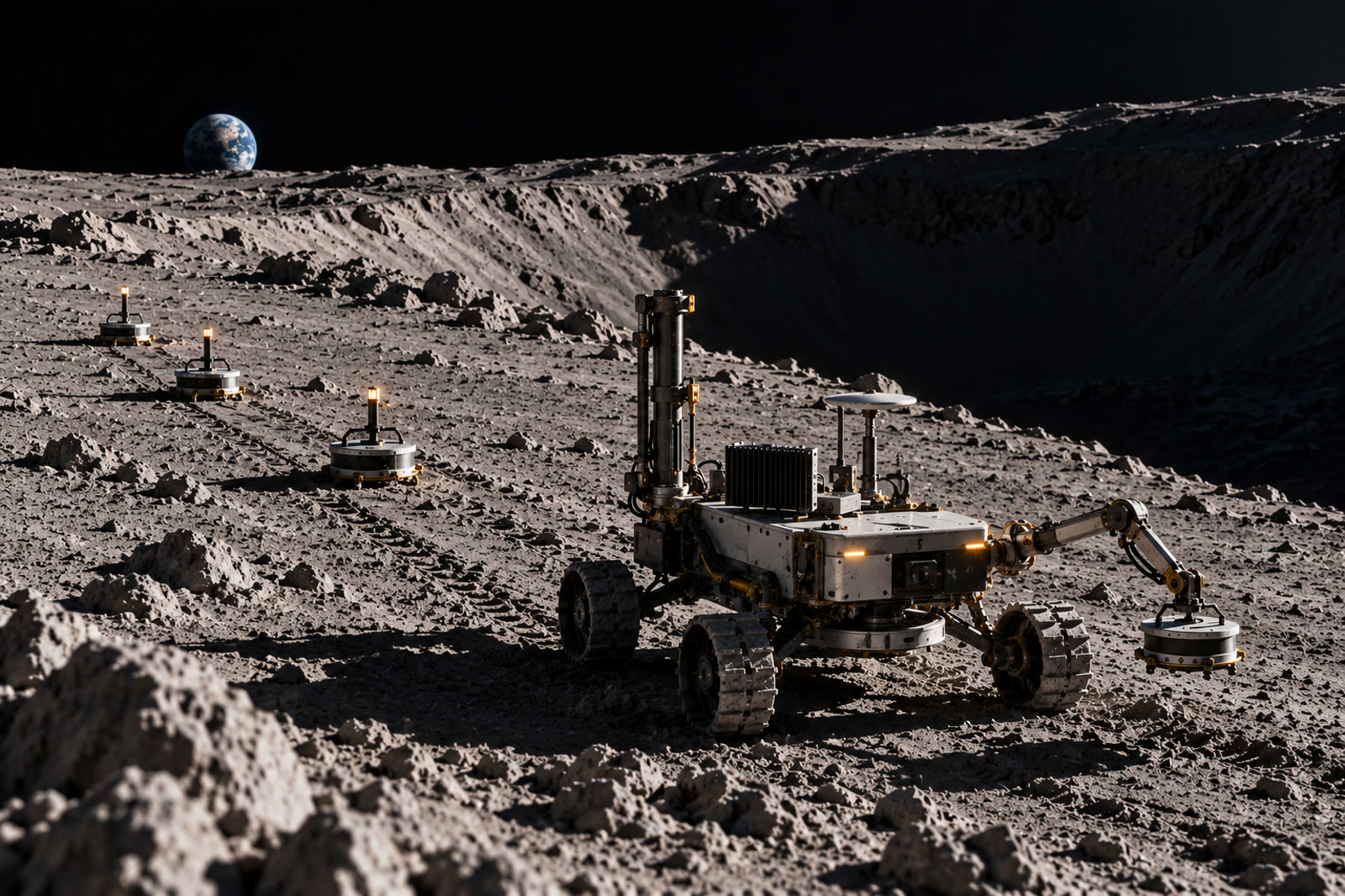
WOK micro-rover on the lunar surface near a crater rim: drill mast, sensor mast, arm placing a geophone pod, three more pods in a line behind it, Earth low on the horizon
FIG. 01 — WOK placing the fourth pod of a survey line. Drill mast forward, source plate stowed beneath the chassis, pods 1 to 3 already seated along the traverse. WOK-RENDER-001 · CONCEPT ART
// 02 Operating Concept
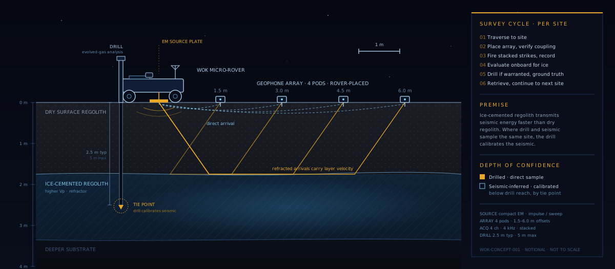
WOK survey site in cross section: rover with source plate and drill, four-pod geophone line, refracted arrivals through dry regolith into ice-cemented regolith, drill tip at the calibration tie point
FIG. 02 — Survey site cross section. Refracted arrivals carry the ice-cemented layer's velocity. The drill tip in that layer is the calibration tie point. WOK-CONCEPT-001 · NOTIONAL · NOT TO SCALE
// 03 Survey Cycle — Per Site

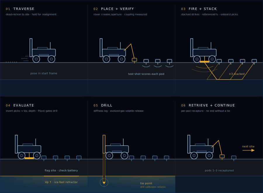
The vehicle runs the cycle below autonomously at each waypoint in an uploaded plan. Any critical fault drops the vehicle to a SAFE state with the array stowed and the drill parked, where it waits for ground.

STEP 01

Traverse to Site

Dead-reckoned drive to the next waypoint in a persistent start frame. Ground can hold the vehicle after a move for a pose check and realignment before anything is placed, so site stamps stay honest over a long traverse.

STEP 02

Place the Array, Verify Coupling

Four geophone pods are placed along a line to create the survey aperture. A low-energy test shot scores each pod's actual ground coupling before data is taken. Poorly seated pods are reseated within bounded attempts, and coupling is recorded as a measured condition, not assumed from a mechanism endstop.

STEP 03

Fire and Stack

Repeatable strikes from a compact electromagnetic source, recorded against a hardware-referenced zero time and stacked per site. First-break arrivals are picked onboard for every pod.

STEP 04

Evaluate Onboard

The picks are inverted onboard for refractor velocity and layer depth. The site is flagged on the probability that the refractor is ice-fast, and that flag, with battery state, gates the drill decision without a ground round trip.

STEP 05

Drill if Warranted

A drill cycle logs a stiffness profile with depth and runs evolved-gas volatile analysis on the sample. The release temperature classifies how the water is bound, which matters for extraction cost, not just presence.

STEP 06

Retrieve and Continue

Pods are retrieved with per-pod recapture confirmation and the vehicle moves on. A mission cannot end without at least one drill: the sequencer returns to its best-scoring site for a calibration tie, because that tie is what anchors every inferred claim across the survey.

Six-panel storyboard of the WOK survey cycle: traverse, place and verify the array, fire and stack, evaluate onboard, drill, retrieve and continue
FIG. 03 — One site, six states. Amber marks the active element in each panel. The ice-cemented layer lights once the onboard inversion flags it. WOK-CYCLE-001
// 04 What Exists Today
FLIGHT SOFTWARE

Six Apps on NASA cFS

Mission sequencer, navigation, geophone array, seismic acquisition and source control, drill, and health/FDIR, on the core Flight System (Draco). All hardware access goes through a per-subsystem hardware abstraction layer; the flight-hardware side of that layer is a documented porting boundary.

VERIFICATION

End-to-End Missions in Simulation

Complete multi-site missions run against a physics simulation in which one shared subsurface model feeds both the seismic and drill instruments. A correct inversion of the synthetic seismic agrees with what the synthetic drill finds, so onboard algorithms are checked against known ground truth, not against themselves.

DATA PRODUCTS

Pose-Stamped, Reprocessable

Per-shot raw traces, per-site stacks with picks, per-site coupling records, and per-cycle drill logs with stiffness and evolved-gas curves. Every product carries the surveyed site pose. Ground analysis fits a velocity-to-ice transfer function from the drill ties and ranks prospects as confirmed or inferred.

GROUND SEGMENT

Console, Dashboard, Analysis

Command console with full test suites and file downlink, a live web dashboard of the mission state machine and telemetry, and site-analysis tooling for refraction inversion, tie points, and prospect ranking. Plans are ground-uploadable, including per-waypoint drill and recalibration flags.

Validated In Simulation
Multi-Site Autonomous Survey Missions
Measured Per-Pod Ground Coupling
Onboard Refraction Inversion & Drill Gate
Ground-Commanded Pose Realignment
// 05 Traceability to SIDA
Capability Tier
Tier 1
Prospecting-class: compact mobile source, small sensor array, method validation and shallow-deposit reconnaissance, calibrated against co-located direct sampling.

The Subsurface Ice Deposit Assessment page defines the capability class without naming a vehicle. WOK is the first-tier instance of it: the vehicle that validates the method and the calibration discipline before larger sources and longer arrays are worth building.

The table maps each SIDA functional requirement to how WOK addresses it today. Where the prospecting tier cannot fully meet a requirement by design, that is stated rather than softened.

ReqFunctionHow WOK addresses it
SIDA-F-001 Depth of investigation Drill samples directly to 5 m. The refraction survey infers layer velocity and interface depth below drill reach, in the band a small-aperture array can resolve. Deposit-scale tens-of-meters depth is the next tier's job.
Partial · by tier
SIDA-F-002 Deposit geometry Per-site refractor depth and velocity; lateral variation emerges across sites in a survey plan. Presence and depth class, not full 3-D extent.
Partial · by tier
SIDA-F-003 Ground-truth calibration The mission-success gate. Seismic and drill at the same pose form a tie point; the sequencer will not end a mission without one, and the velocity-to-ice transfer function is fit from ties and carried into every extrapolated claim.
Enforced onboard
SIDA-F-004 Uncertainty quantification Per-pick confidence, stack coherence, coupling scores that deweight weak channels, a probabilistic ice flag onboard, and confirmed-versus-inferred labels on every ranked prospect.
Carried in products
SIDA-F-005 Survey repeatability Every product is stamped with surveyed pose in a persistent frame with ground-commanded realignment. Archived formats are documented for independent reprocessing, so later missions can densify or repeat coverage.
Designed in
// 06 Key Parameters
ALL VALUES NOTIONAL · TO BE REVIEWED · SET BY SIMULATION BASELINE, NOT FLIGHT HARDWARE

Source

TypeElectromagnetic, plate-coupled
ModesImpulse · Swept-sine
Energy classTens of joules / strike
Stacking3 strikes / site (default)
Coupling checkLow-energy test shot

Array

Pods4 geophone pods
Offsets1.5 · 3.0 · 4.5 · 6.0 m
PlacementRover-placed · retrievable
CouplingMeasured per pod

Acquisition

Channels4
Sample rate4 kHz
RecordSeconds-long
Zero timeHardware-referenced
Onboard picksSTA/LTA first break

Drill & Platform

Depth2.5 m typical · 5 m max
LogsDepth · WOB · torque · ROP
VolatilesEvolved-gas vs temperature
PlatformMicro-rover class
OperationsAutonomous multi-site
// 07 Fleet Context

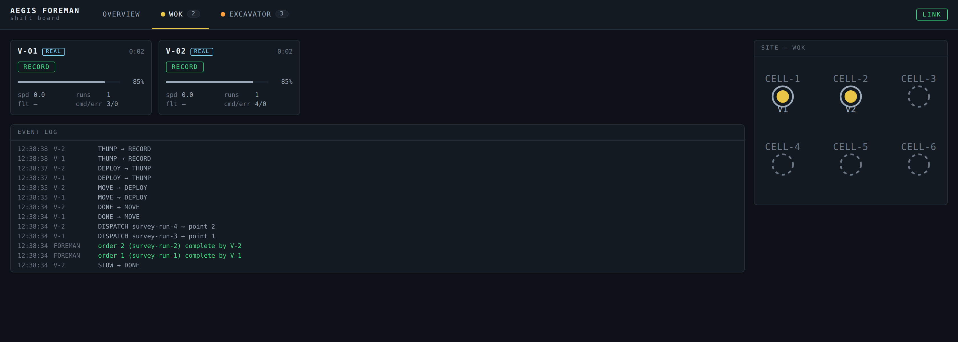
WOK is not a standalone instrument demonstration. It already runs as a vehicle class inside the Aegis surface-operations stack: the same flight software binaries are dispatched by the fleet coordinator, report through the Foreman shift board, and complete survey orders on telemetry, not on a timer. The mixed-fleet surface operations page documents that demonstration with rover, tanker, and WOK assets working one scenario.

Foreman shift board WOK fleet tab: two vehicles tagged REAL in RECORD mode, with the event log showing completed survey orders and immediate re-dispatch.
Foreman shift board, WOK fleet tab. Two vehicles tagged REAL in RECORD, survey orders completing and re-dispatching.
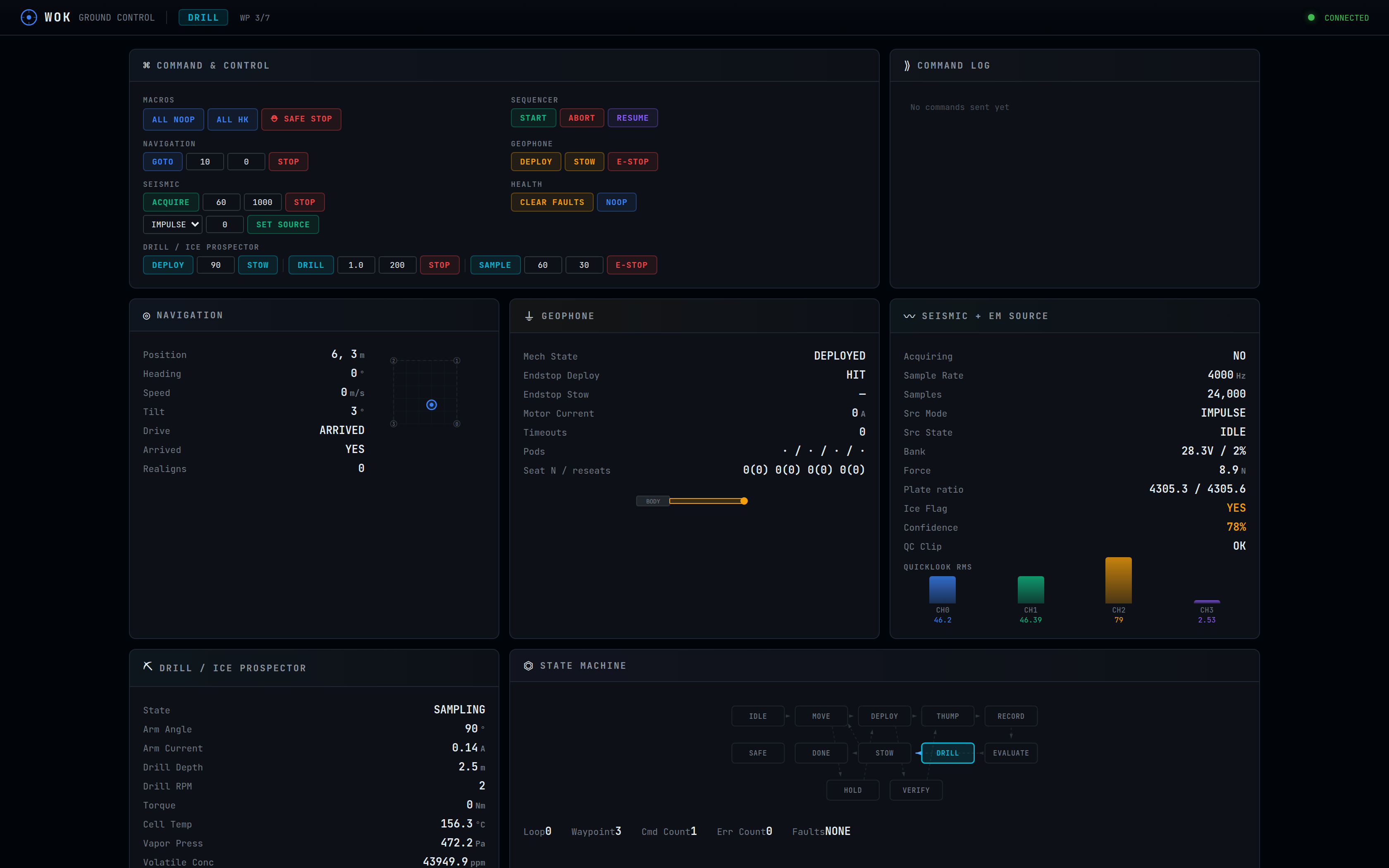
WOK ground control dashboard showing the live mission state machine and telemetry panels.
WOK ground dashboard. Live mission state machine and telemetry from a running flight-software instance.
// 08 Open Questions — Seeking Expertise
Program Context
Open
Flight software and vehicle systems remain with Aegis Station. The geophysics of survey design, methods, and validation is where outside expertise is sought.

The software proves the choreography and the calibration discipline. It does not settle the geophysics. These are the questions a collaborator would be asked to own.

Question 01

Survey Design on a Small Rover

Which acquisition parameters are worth having on a micro-rover: pod count and spacing, stack count, sweep versus impulse, and how much of that should adapt onboard to what the first shot shows.

Question 02

Resolution of a Small-Aperture Array

What a four-pod, six-meter line can and cannot resolve in lunar regolith: depth of investigation, velocity contrast needed for a confident refractor pick, and the failure modes of a thin ice-cemented layer.

Question 03

Interpretation and Validation

How to validate the onboard evaluation in relevant conditions, such as regolith simulant testbeds, and what a defensible velocity-to-ice-content transfer function looks like with a handful of drill ties.

Question 04

Coupling in Vacuum Regolith

How a plate source and rover-placed pods actually couple to dry, electrostatically active regolith, and whether the low-energy coupling check the software performs today measures the right thing.

Discussion welcome through the engagement page.